Unlike their early predecessors, today’s electronic trading floors demand reliable 24/7/365 mission critical support. Seeking close proximity to financial hubs and exchanges to spur low-latency transmission and expedite trades, these environments are typically attracted to middle-aged, urban high-rises. But, designed prior to the electronic age, most urban high-rises don’t have the MEP infrastructure to support such high-demand operations. A far cry from a trading floor’s 20 to 30 watts/sq ft requirement, a typical urban high-rise today offers just 5 to 9 watts/sq ft with cooling and space limitations to match. So, what’s a trading floor to do?
Negotiating with building management for additional electrical and mechanical resources typically fails due to existing building constraints or results in a high penalty for after-hours use. However, the allocation of additional space in a building’s mechanical room or on the rooftop may be all that’s needed. Using a single-source MEP and technology consultant can help turn even a small, back-of-house space into a fully-functional environment with the necessary robust infrastructure.
The Chicago branch of Bank of Montreal, Ontario (BMO) is a case in point. Before leasing the top three floors of the city’s 36-year-old Harris Bank building, BMO hired MEP and technology consultants Environmental Systems Design (ESD), Chicago, to evaluate the existing infrastructure and create a plan for the bank’s move-in.
In addition to the mechanical and electrical infrastructure upgrades needed for daily operation, the Bank bank had two additional requirements for its back-up support: (1) to maintain at least one hour on all computer systems in an effort to resolve pending trades or transactions; and (2) a minimum of two hours on the telecom side to complete phone calls and outstanding communications.
Using the initial building analysis, energy modeling, a thermal study, and creative engineering techniques, ESD designed the mechanical, electrical, and back-up systems infrastructure needed to support BMO’s high-performance operations prior to its move-in last year.
Mechanical and Electrical Solutions
While the downtown Harris Bank building was the location of choice for BMO, its mechanical and electrical infrastructure was already fully utilized by existing core building systems. In order to support the trading floor’s additional daily electrical needs, new utility power feeders had to be wired from the underground utility vault all the way up to the bank’s electrical room on floor 36, which houses the new electrical room contains the switchgear, automatic transfer switches, and the UPS modules to support BMO’s critical functions.
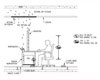
Uninterruptible power is supplied to the tenant’s proprietary building management system (BMS), the data center and telecom rooms, supplemental cooling fans, and chilled water circulators. UPS power is also linked to each of the trading floor’s workstations, designed for eight to 12 monitors, plus the communications and Turret Phone System (see figure 1).
The mechanical infrastructure specified to support BMO’s operations included three 50-ton, chiller modules installed in the building mechanical room located on floor 38 directly above the trading floor space. The system’s modular design allowed for the chiller components to be conveniently transported via freight elevators up to the building’s top floor. In order to minimize energy expenditure when possible and to take advantage of Chicago’s seasonally cool temperatures, a waterside economizer was employed via closed-circuit fluid cooler. The system was designed to maintain a fluid temperature set point of 50ºF, therefore increasing the availability range of the economizer cycle and requiring less energy when in mechanical cooling. To complement the inherently flexible staging capacity of the modular chiller, a variable primary pumping scheme was employed to maximize energy efficiency.
The mechanical cooling plant was designed for concurrent maintainability and N+1 redundancy; however unforeseeable catastrophic failures of mission critical support systems were also considered. For extra peace of mind, the designers were able to repurpose the medium pressure ventilation loop that runs directly over the data center space as a low cost solution for emergency cooling. A rise in the temperature of the data center to 80ºF will trigger the base building air handler to start, and motorized dampers on the building’s ventilation loop to divert airflow from the office areas into the data center space and its adjacent electrical room.
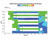
During design, ESD conducted a thermal study to map out the ideal location for high-density cabinets within the server room for maximum cooling effectiveness (see figure 2). Room layouts challenged by existing building constraints resulted in 4-ft. cold aisles, as opposed to the preferred 6-ft. aisles, but with the flexibility to go to a hot-aisle containment system down the road.
A Back up to Bank on
While additional space was leased from the building to accommodate BMO’s supplemental infrastructure requirements, there wasn’t a suitable location for a generator and associated fuel storage to back up the incoming utility power feed. Instead, ESD tailored the UPS system capacity to meet the two-hour emergency electrical runtime requirement. Analogous to the electrical battery reserve, an ice storage system was integrated to carry the cooling load associated with the data center and trading floor operations during a utility power outage.
During normal operations, the BMS continually monitors the state of incoming power to BMO’s floors. When it detects a situation where the UPS is on battery power and the system cooling fluid temperature rises three degrees above the set point, it goes into emergency mode operation. Commanding a diverting valve, the BMS will automatically bring the ice storage tank into the cooling system loop to replace the chiller to sustain the cooling load.
The ice re-generation schedule is based on real-time tank charge level, and is regulated by the BMS. With a well-insulated tank, the system has an idle decay rate of less than 0.1 percent a day. To maintain the necessary capacity, the chiller plant switches to ice generation mode when the tank percentage charge level falls to the specified set point. Once the tank is replenished, the chiller reverts to its previous operational mode, either economizer or refrigeration. Using reserve ice, the system can carry the entire supplemental cooling load for up to four hours, if necessary.

Installing the roof-mounted fluid cooler proved to be another challenge for the building team. Design-build contractor Executive Construction, Inc. (ECI), Chicago, worked off-hours and closed a main downtown Chicago street to hoist the device via helicopter lift. The fluid cooler had to be lifted in pieces, and re-assembled atop the structural steel framing while the helicopter hovered above (see figure 3).
“Working together with ESD, we were able to accommodate the client’s back-up needs without a generator -that’s a credit to the team’s collaboration,” said David Hetrick, vice president, ECI. “Without this additional chilled water from the ice tank, it would have been a matter of minutes until the server room overheated.”
As with most high-performance renovations, upfront project team collaboration is crucial to meeting both landlord and tenant requirements. For BMO, operational success depended on it.
“Accommodating the logistical challenges of the building, meeting the design requirements of the client and maintaining the overall project budget was a collaborative effort between ECI and ESD,” said Hetrick. “The benefit of sharing information upfront allowed BMO to get a better understanding of the infrastructure they’re getting to support their systems. In addition, the design and construction team got a better idea of the driving reasons behind their needs.”
The Next Generation of Trading Floors
While today’s trading firms have to re-purpose yesterday’s high-rise urban centers themselves, tomorrow’s traders may find their ideal spaces already pre-configured. Because trading and data center real estate is currently growing beyond that of the other market sectors, developers are looking to preemptively accommodate the influx of new high-tech leases.
Employing firms like ESD, developers are now renovating existing high-rises and building new ones to meet a minimum trading floor capacity of 30 watts/sq ft and a supporting data center capacity of 200 watts/sq ft, including upgraded MEP systems and dedicated generators for each floor. These buildings will likely house the data centers on the bottom floors, with the trading environments and their firm’s corporate offices on the top floors.
Ushering in a new era of 24/7/365 mission critical support, these facilities will surely use building analysis, energy modeling, and creative engineering techniques as employed at BMO to turn the typical middle-aged urban high-rise into a high-performance facility with the MEP systems and the data processing capability to match. So, what’s a trading floor to do?


