|
|
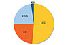
Figure 1. Projected share of network ports – 2015. 1G/10G/40G/100G Networking Ports Biannual Market Size and Forecasts © Infonetics Research, April 2011 Click here to enlarge |
Data centers regularly undertake their own great migration, to ever higher speed networks. Applications from development software and ERP systems to consumer content, medical and academic records, and a host of others are continously driving demand for greater bandwidth, and the network must keep pace.
Unimaginable a decade ago, 10G is now common in larger enterprises. Several 40G core, edge, and top of rack (ToR) switches are on the market today, including equipment from Force10, Cisco, Arista, Extreme Networks, Hitachi, and Blade Networks. Cisco, Alcatel-Lucent, Brocade, and Juniper Networks have introduced 100G equipment as well. By 2015, higher-speed Ethernet will have about a 25 percent share of network equipment ports, according to Infonetics Research (see figure 1). The need is clear: a higher-speed Ethernet migration plan is rapidly becoming a matter of survival.
|
|
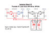
Figure 2. IEEE 850 nm OM3 and OM4 Ethernet Performance Specifications.Click here to enlarge |
Not every network is optimized for this inevitable growth. Yet, organizations that anticipate migrating can create a simple, cost-effective migration path by installing a structured cabling system that can support future 40/100G networking needs. An ideal system will include the following:
• One simple, modular connectivity solution for legacy 1G and 10G applications that is also compliant to 40G and 100G
• One standardized connector theme able to support future high-bandwidth applications
• Preconnectorized components compliant to all current and anticipated industry standards
|
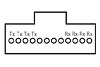
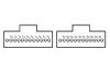
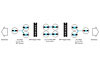
| Figure 3. 40G 12-fiber MTP connector. Pins 1-2-3-4 are for Transmit (Tx), and 9-10-11-12 are for Receive (Rx). Pins 5-6-7-8 are not used. Click here to enlarge |
A foundational understanding of laser optimized multimode (LOMM) 40/100G structured cabling and awareness of the pros and cons of 12- vs. 24-fiber MPO/MTP cabling is necessary to prepare for higher-speed Ethernet. (MTP is a high-performance MPO connector manufactured and trademarked by US Conec, Ltd. The authors use the term MTP to refer to all MPO/MTP interfaces and connectors.)
UNDERSTANDING 40/100G
Planning for migration to higher speed Ethernet can be daunting. The standards for 40G and 100G are significantly different from previous generations; active equipment and transmission methods are unique. Even polarity takes on a new importance.
|
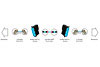
| Figure 4. 100G 2x12-fiber MTP connector. Pins 2-11 on 1st cable are for Transmit (Tx), and pins 2-11 on the 2nd cable are for Receive (Rx). Pins 1 and 12 are not used. Click here to enlarge |
IEEE AND TIA STANDARDS
Structured cabling systems design is always guided first by standards. IEEE creates the standards that define performance parameters, while TIA writes those that define how to apply the parameters to structured cabling systems. Familiarity with these standards will help designers create data center infrastructure that better supports network upgrades.
|
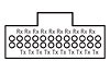
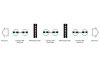
| Figure 5. 100G 24-fiber MTP connector – IEEE recommended option. Pins 14-23 are for Transmit (Tx), and pins 2-11 are for Receive (Rx). Pins 1, 12, 13, and 24 are not used. Click here to enlarge |
IEEE 802.3ba 40Gb/s and 100Gb/s Ethernet is the only current standard that addresses the physical layer cabling and connector media maximums for 40G/100G fiber channel requirements (the standard does not address copper UTP/SCTP categories). IEEE 802.3ae 10Gb/s Ethernet covers the fiber protocols for 10G transmission. Figure 2 highlights some differences between the two types, including the tighter link-loss parameters with 40/100G. To achieve proper performance throughout the channel, each system component must meet lower loss limits as well.
TIA-942 Telecommunications Infrastructure Standard for Data Centers establishes design criteria including site space and layout, cabling infrastructure, tiered reliability, and environmental considerations. The standard recommends using the highest capacity media available to maximize infrastructure lifespan. 10G equipment is the most frequently installed today, but as noted in the Infonetics Research forecast, 40G and 100G Ethernet will soon grow to become common networking speeds.
ACTIVE EQUIPMENT INTERFACES
|
| Figure 6. 1/10G Channel 12-fiber configuration. Click here o enlarge |
Fiber connectivity in higher-speed active equipment is being condensed and simplified with plug-and-play, hot-swap transceiver miniaturization. 1G and 10G networks commonly utilize the GBIC (gigabit interface converter). For 8G Fibre Channel SAN and OTU2, as well as some 10G, the transceiver is the SFP+ (small form-factor pluggable plus). Interfaces for 40G and 100G active equipment include QSFP (quad small form-factor pluggable), CFP and CXP (100G form-factor pluggable).
MPO/MTP is the designated interface for multimode 40/100G, and it’s backward compatible with legacy 1G/10G applications as well. Its small, high-density form factor is ideal with higher-speed Ethernet equipment.
|
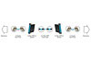
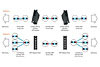
| Figure 7. 40G Channel 12-fiber configuratiom Click to enlarge |
PARALLEL OPTICS
LOMM 40G and 100G Ethernet employ parallel optics. Data are transmitted and received simultaneously on MTP interfaces through 10G simplex transmission over each individual strand of the array cable. Current IEEE channel/lane assignments for active equipment interfaces determine the transmission methodology (see figures 3-5).
POLARITY
TIA-568-C.0 Generic Telecommunications Cabling for Customer Premises includes three MTP array cable polarity methods—A, B, and C. In addition, TIA will soon be releasing two new addenda—TIA-568-C.0-2 and TIA-568-C.3-1—to specifically address the polarity and cabling requirements needed to support 40G and 100G applications. As the market moves toward 40G and 100G networking speeds, polarity becomes more and more important. With multiple channels within a single connector, all components must be manufactured with the same polarity; differences cannot be reconciled by flipping or switching connector position in the field. Many end users prefer Method B, as it has the same “straight-through” MTP array cord on both ends of the channel, which greatly simplifies upgrades.
12- VS. 24-FIBER CABLING INFRASTRUCTURE
|
| Figure 8. 100G Channel 12-fiber configuration Click here to enlarge |
All higher-speed Ethernet networks use 12- or 24-fiber MTP trunks. The differences between the two schemes determine how to best optimize a cabling plant when upgrading. These differences include migration, density, congestion, and cost.
MIGRATION
Figures 6-11 show 12- and 24-fiber system configurations for 1G-100G networks. With the 40G 12-fiber legacy configurations, a second trunk and another set of array harnesses will be needed to achieve 100 percent fiber utilization. For 100G, these additional components will be required for any 12-fiber legacy upgrade. On the other hand, with 24-fiber trunks, a single cable can support a 1G-100G channel and will simplify network upgrades immensely. 1G and 10G networks will link the trunks to active equipment with MTP-LC modules and LC duplex patch cords. When equipment is upgraded, modules and patch cords are exchanged for the appropriate new MTP components, with no need to install new trunks. In addition, limiting changes reduces the inherent risks to network security and integrity whenever MAC work is completed.
DENSITY
|
| Figure 9. 1/10G Channel 24-fiber configuration Click here to enlarge |
Higher density connectivity in the enclosure leaves more rack space for active equipment, reducing the total amount of floor space required. 24-fiber cabling has the obvious advantage. If the active equipment is configured for 24-fiber channel/lane assignments, enclosures can have twice as many connections with the same number of ports compared to 12-fiber (or the same number of connections using only half the ports, see figure 12).
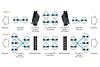
For 40G networks, a 24-fiber MTP wiring scheme can deliver true 100 percent fiber utilization—no dark fibers or empty pins. With this configuration, density is doubled at the adapter plate/enclosure side as compared to 12-fiber 40G wiring schemes.
|
| Figure 10. 40G Channel 24-fiber configuration options. Click here to enlarge |
The flip side of density is congestion. The more connectivity that runs in the same footprint, the more crowded it can become at the rack or cabinet. Here again, 24-fiber MTP trunks offer a huge benefit. Anywhere there’s fiber, from within the enclosures to cable runs that connect different areas of the network, will have just half the number of cables vs. 12-fiber. Runs carry a lighter load, fibers are easier to manage, and improved airflow reduces cooling costs.
COST
12-fiber configurations may enable the continued use of existing trunks when equipment is upgraded, if 12-fiber MTP-MTP trunks are available, but will likely require additional trunks, more connectivity components, and other network modifications. In the long run, it’s many times more expensive to retain these trunks than to upgrade to 24-fiber up front.
|
| Figure 11. 100G Channel 24-fiber configuration Click here to enlarge |
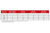
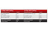
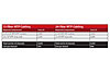
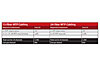
Figures 13 through 15 present 12- vs. 24-fiber deployment cost comparisons for a 24-channel/48-fiber 10G network, 40G upgrade, and 100G upgrade (components only).
|
| Figure 12 Click here to enlarge |
The tables show that the migration cost savings with 24-fiber trunks increase at higher networking speeds. For the 10G network, cost is almost equal, but 24-fiber trunks reduce end-user costs about 10 percent for a 40G upgrade, and almost 25 percent for a 100G upgrade. Factor in the labor costs of installing additional trunks and other components with 12-fiber, and the difference is even greater.
CONCLUSION
|
|
Figure 13. Cost for 24 channel 10G cabling infrastructure. Click here to enlarge |
Being prepared for 40/100G is essential; within a few short years higher-speed Ethernet will be common in data centers across all types of organizations. Installing a high-performance 24-fiber 40/100G MTP system will provide several benefits when the network is upgraded:
• Fewer connectivity components to be replaced or added simplifies migration and reduces costs for both components and installation
• Higher density connectivity leaves more rack space for active equipment
• Fewer trunks reduce cable congestion throughout the data center
|
| Figure 14. Upgrade cost to 24 channel 40G cabiling infrastructure. Array cord configuration—Option A in Figures 7 and 10. Click here to enlarge |
In short, a 24-fiber higher-speed Ethernet MTP system will future-proof network cabling, lower the cost of ownership, and maximize return on investment.
|
|
Figure 15. Upgrade cost to 24 channel 100G cabling infrastructure. Click here to enlarge |


