
The 2012 NFPA 70E “Electrical Safety in the Workplace,” effective this March, contains revisions requiring stricter arc-flash protection, making now a good time to brush up on the importance of short circuit, coordination, and arc-flash studies. Whenever a fault occurs in an electrical power system relatively high currents flow, producing destructive energy in the forms of heat and magnetic forces. When an electrical fault exceeds the interrupting rating of a protective device or the fault-withstand rating of electrical equipment, the consequences can include injury or death, fire, damaged electrical equipment, OSHA fines, and costly downtime.
|
|
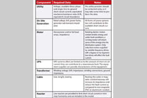
Table 1: Short circuit study components |
A short circuit study (SCS) is required to establish minimum equipment ratings for power system components to withstand the mechanical and thermal stresses that occur during a fault and its interruption. A study will identify any problem areas that could pose a safety risk in the event that a fault does occur. SCSs also ensure that an electrical system meets the requirements of National Electric Code (NEC) articles 110.9 Interrupting Rating, 110.10 Circuit Impedance and Other Characteristics, and 110.16 Flash Protection.
The calculations that are the basis of an SCS involve the reduction of the power distribution system to a Thévenin equivalent circuit at each bus. These calculations can be done by hand, but since they are very tedious for today’s complex distribution systems, they are usually performed using specialized software. The software model is used to calculate the resultant fault current at each bus in the system.
There are five different types of bolted faults in a three-phase power system including:
• Phase-ground
• Phase-phase
• Phase-phase-ground
• Three-phase
• Three-phase-ground
|
|
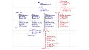
Figure 1: Example of a short circuit software model one-line
|
Of all of these, the three-phase fault produces the highest fault currents. Typically, SCS results include both three-phase and single-line-to-ground faults to produce a worst-case scenario.
In order for the electrical distribution system analysis software to produce reliable results, the electrical distribution system being analyzed must be modeled accurately. Table 1 provides the basis for components that must be included in the study.
The maximum short circuit fault current is recorded at each bus in the distribution system. The calculated fault currents are used to specify the required ratings for new equipment and to evaluate the adequacy of the existing system components to withstand and interrupt these high magnitude currents. Once the electrical distribution system is modeled, proposed changes in system configuration can be analyzed in order to determine if any equipment must be upgraded to support the proposed changes. An accurate SCS is also a requirement for protective device coordination studies and arc-flash hazard analysis.
Following the SCS is the protective device coordination study (PDCS), which determines the correct overcurrent devices and adjustments to their settings to maximize selectivity and power system reliability. In a perfectly coordinated system, all faults are cleared by the nearest upstream protective device. This minimizes the portion of the electrical distribution system interrupted and isolates the fault to simplify troubleshooting.
As with an SCS, a PDCS is usually performed using the same specialized integrated software that is used for the short circuit, load flow, and arc-flash calculations. Protective device types, ratings, and settings can be incorporated while the short circuit model is built or added after the initial study is completed. The use of computerized calculations allows engineers to evaluate a number of settings and configurations in a short period of time, thereby allowing equipment selection and settings to easily be fine-tuned to achieve the best possible coordination.
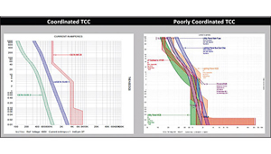
A time current curve (TCC) is developed for each circuit in the power distribution system where coordination could be problematic (such as situations where upstream and downstream protective devices have similar current ratings and trip characteristics). The TCC includes a comparison of the largest downstream overcurrent devices for the largest loads that may not coordinate with their upstream feeders.
Generally, a relatively small protective device will coordinate well with a much larger upstream device. For example, a 50-amp (A) branch circuit fuse fed by a 400-A main fuse. All fuses, breakers, electromechanical or electronic relays, and trip devices are included. Transformer and cable damage curves are also included to verify that the protective devices trip before the equipment is damaged. Transformer inrush points must also be included to verify that the protective device feeding the unit will not operate when the transformer is energized.
Device selection and settings from the database are reviewed to determine if changes are required to improve coordination. However, in many cases protective device coordination is a matter of compromise and requires making selections that result in the best coordination that can be achieved with the devices that are installed. Where power system reliability must be maximized and strict coordination is required, electronic relays and trip devices are used.
|
|
Table 2: Time current curve examples |
Short circuit and coordination studies involve the analysis of bolted faults. There is another type of fault, the arcing fault, which is extremely dangerous to personnel servicing live equipment. Arcing faults are caused by the inadvertent connection of energized electrical phases or an electrical phase and ground through the air, which creates a small explosion. An arc fault explosion and resulting flash can reach temperatures of 35,000°F (the sun is approximately 10,000°F). A typical 800-A distribution panel with 15-kA available short circuit current is capable of producing an arc fault explosion equivalent to 132g of dynamite. These faults are also more dangerous than bolted faults because they have a relatively lower current due to the air and can take longer to be cleared by protective devices.
NEC Article 110.16 specifies labels that must be placed on all electrical equipment “likely to require examination, adjustment, servicing or maintenance while energized” warning of the arc-flash hazard.
Equipment must also be clearly labeled with how much fault energy is available and the required personal protective equipment (PPE) that must be worn if performing energized work. PPE is extremely important for safely performing energized work, but it is not intended to encourage it. Whenever possible it is always safer to perform work de-energized, as PPE will only reduce the intensity of the blast, it will not completely shield the wearer from injury.
Computer software can calculate the arc fault energy available at each bus after the system is analyzed from a short circuit standpoint. Using this information, the required level of protection for performing energized work can be determined. The computer software can also be used to determine if adjustments to trip device or relay settings or fuse selection can reduce the arc-flash hazard category to a lower, less restrictive level. Such analysis should be included in any arc-flash hazard study. Often, the engineering firm performing the study will also provide the arc flash warning labels for each piece of equipment after the analysis is completed.
State-of-the-art protective devices can minimize or eliminate unnecessary outages due to compromised coordination. If project requirements demand strict coordination, electrical equipment selection, specification, and layout may be affected and should be considered as early in the project as possible. Selection of the wrong type of equipment may negate the ability to take advantage of the technological advances discussed above. A short circuit and coordination study followed by an arc-flash hazard analysis will ensure that your electrical system is performing safely and reliably and is compliant with the NEC and NFPA 70E.
Also, both the engineer and the client should be sure that the scope of work for the short circuit, coordination, and arc flash study is clearly defined at the start of the project. The engineer and client should also establish strong communication so that any missing information required to complete the study can be relayed without harming the project schedule.
The inevitable changes made to every power distribution system throughout its life will affect how it reacts during a fault event. Therefore it is important to keep the short circuit, coordination, and arc flash studies up to date after significant system upgrades or additions. Also, ensuring that all employees are properly trained before servicing or operating any equipment and keeping adequate PPE readily available at all times will minimize the chance that there will be any incidents.
This article contains excerpts from the IEEE/Wiley textbook, Maintaining Mission Critical Systems in a 24/7 Environment, by Peter M. Curtis. Consult the book for more information regarding this subject as well as many others relating to the mission critical engineering field. The book can be purchased here: http://www.wiley.com/WileyCDA/WileyTitle/productCd-0470650427.html with the 20 percent discount code AUT27. This material is also offered as part of the Foundations of Mission Critical Infrastructure certification. Point your browser to http://dc-professional.com/ for more information on the course offerings.

